What is an RTD? Resistance temperature detector guide
Sep 03, 2026Those are the definitions. What decides whether your measurement is any good is the error budget around them, the way an RTD fails, and what has to appear on the purchase order.
Published 3 September 2026. Reviewed by the Focusens technical department.
RTDs are interchangeable between manufacturers because the curve is standardised rather than proprietary. IEC 60751:2022, edition 3.0, published 27 January 2022, specifies the resistance versus temperature relationship for industrial platinum resistance thermometers and platinum temperature sensors, referred to the International Temperature Scale of 1990.
The metrological basis for that scale is documented in the BIPM's Guide to the Realization of the ITS-90, chapter 5, Platinum Resistance Thermometry. Two equations do the work. Above 0 °C: R(t) = R₀ · [1 + A·t + B·t²] Below 0 °C, a third term is added:
R(t) = R₀ · [1 + A·t + B·t² + C·(t − 100)·t³] with A = 3.9083 × 10⁻³ °C⁻¹, B = −5.775 × 10⁻⁷ °C⁻², and C = −4.183 × 10⁻¹² °C⁻⁴.
R₀ is the resistance at 0 °C, so 100 Ω for a PT100 and 1000 Ω for a PT1000. Everything in the tables below comes from those equations, and you can reproduce any value in a spreadsheet.
| Temperature | PT100 | PT1000 | Slope at that point |
|---|---|---|---|
| −200 °C | 18.52 Ω | 185.2 Ω | 0.432 Ω/°C |
| 0 °C | 100.00 Ω | 1000.0 Ω | 0.391 Ω/°C |
| 100 °C | 138.51 Ω | 1385.1 Ω | 0.379 Ω/°C |
| 200 °C | 175.86 Ω | 1758.6 Ω | 0.368 Ω/°C |
| 400 °C | 247.09 Ω | 2470.9 Ω | 0.345 Ω/°C |
| 600 °C | 313.71 Ω | 3137.1 Ω | 0.322 Ω/°C |
| 850 °C | 390.48 Ω | 3904.8 Ω | 0.293 Ω/°C |
Values calculated from the IEC 60751 coefficients above.
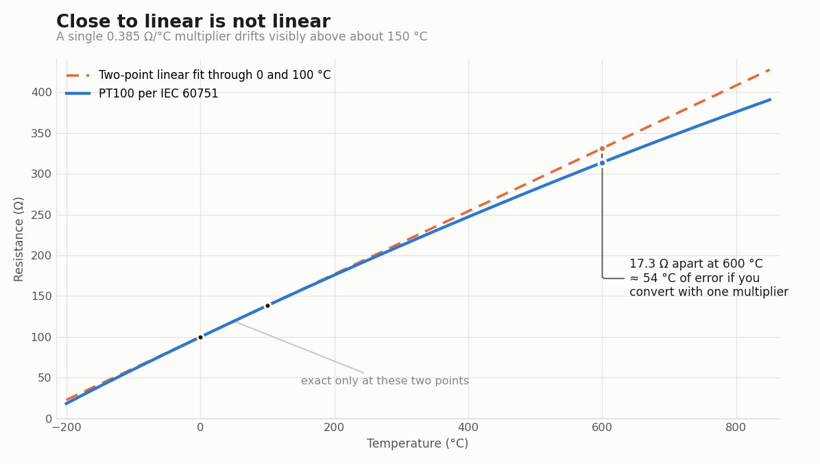
Calculated from the IEC 60751 coefficients. The dashed line is a two-point linear fit through 0 and 100 °C.
The slope column is the one people skip. The familiar 0.385 Ω/°C figure is an average across 0 to 100 °C, not a constant, and real sensitivity falls by about a quarter between the ice point and 850 °C.
A single-multiplier conversion drifts noticeably above roughly 150 °C. Full lookup values for both PT100 and PT1000 are in the complete resistance table.
Platinum dominates because its resistance-temperature behaviour is repeatable over a wide span and it resists contamination. Nickel and copper elements exist and are cheaper, with narrower usable ranges. Within platinum, the choice is nominal resistance and construction.
| PT100 | PT1000 | |
|---|---|---|
| Resistance at 0 °C | 100.00 Ω | 1000.0 Ω |
| Sensitivity, 0 to 100 °C average | 0.385 Ω/°C | 3.85 Ω/°C |
| Temperature error per 1 Ω of lead resistance | about 2.6 °C | about 0.26 °C |
| Power dissipated at 1 mA excitation | 0.1 mW | 1.0 mW |
| Usual wiring | 3-wire or 4-wire | 2-wire is workable |
| Common construction | wire wound and thin film | mostly thin film |
Both share the same curve shape and the same tolerance classes. Multiply any PT100 resistance by ten and you have the PT1000 value.
What differs is how each behaves once wires and excitation current are attached, which is the next section. If you are choosing between the two for a specific installation, PT1000 vs PT100 goes through the trade-offs.
Construction matters as much as nominal resistance. A thin-film element is a platinum track deposited on a ceramic substrate, small and fast and cheap in volume.
A wire-wound element is a platinum coil in a ceramic or glass body, which survives higher temperatures and, in the glass form, thermal shock.
IEC 60751 assigns each tolerance class a validity range that differs between wire-wound and thin-film elements, so a class is a promise over a stated window rather than a property of the part everywhere.
Check the current edition of the standard for the exact windows before writing a class into a specification.
IEC 60751 defines four classes. The tolerance is expressed in degrees, and it widens with temperature.
| Class | Tolerance formula | At 0 °C | At 100 °C | At 400 °C |
|---|---|---|---|---|
| AA | ±(0.1 + 0.0017·|t|) °C | ±0.10 °C | ±0.27 °C | ±0.78 °C |
| A | ±(0.15 + 0.002·|t|) °C | ±0.15 °C | ±0.35 °C | ±0.95 °C |
| B | ±(0.3 + 0.005·|t|) °C | ±0.30 °C | ±0.80 °C | ±2.30 °C |
| C | ±(0.6 + 0.01·|t|) °C | ±0.60 °C | ±1.60 °C | ±4.60 °C |
Formulas per IEC 60751. Each class is valid only over the temperature window the standard assigns it, and that window depends on element construction. A tolerance class describes the element on its own, at the moment it left the factory.
It says nothing about the wires you connect to it, the current you push through it, or what the transmitter does with the signal. Treating the class figure as the accuracy of your measurement is the most common specification error in RTD work.
A tolerance class is one term in the measurement, and usually not the largest. Here is the arithmetic. A Class A PT100 at the ice point is specified to ±0.15 °C.
One ohm of lead resistance in a 2-wire connection adds about 2.56 °C to the reading, because the slope there is 0.391 Ω/°C and the meter cannot tell sensor resistance from cable resistance. The wiring error is roughly seventeen times the tolerance you paid for.
One ohm is not a hypothetical. Ten metres of 0.5 mm² copper, out and back, is about 0.69 Ω at room temperature, which lands near 1.8 °C on a PT100 and near 0.18 °C on a PT1000.
| Error source | PT100 | PT1000 | Notes |
|---|---|---|---|
| Class A element tolerance at 0 °C | ±0.15 °C | ±0.15 °C | identical, the class is defined in degrees |
| 1 Ω lead resistance, 2-wire | +2.56 °C | +0.26 °C | scales with R₀, not with class |
| 10 m of 0.5 mm² copper, 2-wire | about +1.8 °C | about +0.18 °C | out and back at room temperature |
| Self-heating at 1 mA | small | about ten times larger | PT1000 dissipates 1.0 mW against 0.1 mW |
| 3-wire or 4-wire compensation | removes most or all lead error | same | this is what the extra wires buy |
Three practical consequences follow. Lead resistance is the dominant term in a 2-wire PT100 installation and it swamps the class difference between A and B, so paying for Class A on a long 2-wire run buys nothing.
Self-heating runs the opposite way, because at the same excitation current a PT1000 dissipates ten times the power of a PT100, which is why PT1000 front ends usually drop excitation to a few tenths of a milliamp.
And the two errors have opposite signs in terms of which sensor they punish, so there is no universally better choice, only a choice that fits the wiring.
Self-heating also depends on what surrounds the element. A probe in moving water carries heat away far better than the same probe in still air, so the same current produces a different error in each.
Manufacturers publish a dissipation constant in mW per °C for this reason. Ask for it if your budget is tight enough to care.
Three wiring configurations exist, and the choice is driven by lead resistance rather than by preference. Use 2-wire only for a PT1000 on a short run, or where a degree or two does not matter. The measurement includes your cable and there is no way to subtract it.
Use 3-wire as the industrial default. A third conductor lets the instrument measure and cancel the lead resistance, on the assumption that all three wires have equal resistance.
That assumption holds when the wires are the same gauge, the same length and at the same temperature, and it breaks when someone extends one leg with a different cable.
Use 4-wire for calibration work, laboratory measurement, and any case where you cannot guarantee matched leads. Current flows in one pair and voltage is sensed on the other, so lead resistance drops out of the arithmetic rather than being estimated.
The full wiring diagrams and the error arithmetic for each case are in 2-wire vs 3-wire vs 4-wire RTD.
An RTD that has failed outright is easy. An RTD that is merely wrong is the expensive one. Measure resistance at the terminals with the loop de-energised and compare against the table above.
| What the meter shows | Most likely cause | How to confirm | Action |
|---|---|---|---|
| Open circuit or overrange | Broken element or broken lead | Measure at the sensor head, then at the panel. A break between the two points to the cable | Replace the failed section |
| Near 0 Ω | Short between conductors, often water in a head or a crushed cable | Inspect the head for moisture, check insulation resistance to sheath | Dry and reseal, or replace |
| Plausible but offset by a few degrees, reading high | Lead resistance in a 2-wire loop, or a mismatched third leg | Measure loop resistance of the cable alone with the sensor disconnected | Move to 3-wire or 4-wire, or match the leads |
| Reads correctly cold, drifts high as the process heats | Insulation breakdown at temperature, or moisture inside the sheath | Repeat the measurement hot and cold, watch insulation resistance to sheath | Replace, and check the sheath rating against the process |
| Slow to respond, otherwise correct | Poor thermal contact, insufficient immersion, fouling on the sheath | Compare response against a second probe in the same medium | Improve immersion or clean the sheath |
| Correct at the head, wrong at the display | Transmitter configured for the wrong element or wrong wiring mode | Check whether the input is set to PT100 or PT1000, and to 2, 3 or 4-wire | Reconfigure the transmitter |
The last row catches more faults than most engineers expect. A PT100 on an input expecting PT1000 sees a resistance far below anything in its table and reads at the bottom of the scale or raises a sensor-break alarm, because a PT1000 does not reach 100 Ω anywhere in its range.
An RTD reports the temperature of its own element, which is only the process temperature if you install it so that those two are the same thing. Installation error is routinely larger than element tolerance.
Immerse enough of the probe. Heat conducted along the sheath and out through the mounting pulls the element toward ambient, and the shorter the immersion, the larger that stem conduction error. Give the tip room to sit in flowing process fluid rather than in a dead pocket near a wall.
Put the sensor where the fluid moves. A probe in a stagnant leg measures the stagnant leg.
Watch the thermowell. A well protects the probe and lets you replace it without breaking the process, and it also adds thermal mass and an air gap. A loose fit inside a well can add tens of seconds to the response time.
Keep sensor cable away from motor and drive cable, ground the shield at one end only, and terminate with ferrules rather than tinned bare strands, because a degrading crimp shows up as a slow upward drift in a 2-wire loop.
A part number has to answer six questions before anyone can quote it.
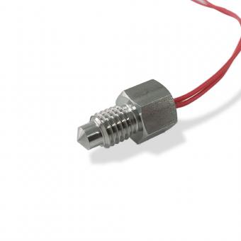
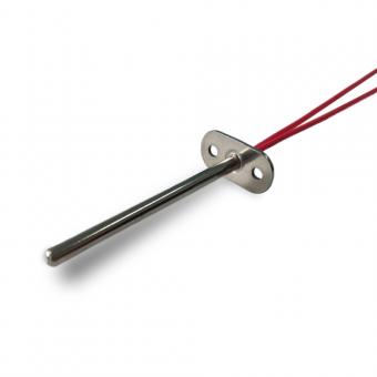
Focusens FWZ series RTD sensors are built with PT100, PT500 or PT1000 elements in three range bands, −50 to 200 °C, −50 to 350 °C and −50 to 600 °C, to DIN Class A or Class B, with SUS304 or SUS316 sheaths and PVC, Teflon, silicone or fibreglass leads.
Insulation resistance is 100 MΩ and response time is around 10 seconds at 0.63τ. The ordering code carries the element type, tolerance class, simplex or duplex build, mounting style, lead material and lead length, so a complete probe can be specified without a drawing.
| Decision | Options | What drives it |
|---|---|---|
| Element | PT100, PT500, PT1000 | wiring length and the front end you already own |
| Tolerance class | Class A, Class B | required uncertainty, and whether wiring error already dominates |
| Element count | simplex, duplex | redundancy or a second independent loop |
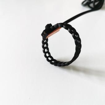
| Mounting | tubular, surface, flange, threaded, spring-loaded, pipe clamp, armoured | how the probe reaches the medium |
| Sheath | SUS304, SUS316 | process chemistry and temperature |
| Lead | PVC, Teflon, silicone, fibreglass, braid shield, plus length | ambient temperature at the cable, not at the tip |
Threaded versions are available in M8×1, M12×1, M14×1, M16×1.5, G1/4 and G1/2. Specifications above are from the Focusens product catalogue. The full range sits in the RTD sensor category, and the PT100 platinum resistance thermometer probe is a typical starting point.
Both change resistance with temperature, and that is where the similarity ends.
| Platinum RTD | NTC thermistor | |
|---|---|---|
| Direction | resistance rises with temperature | resistance falls with temperature |
| Curve | close to linear, defined by IEC 60751 | steeply exponential, defined per part |
| Interchangeability | any compliant PT100 substitutes for another | depends on the part's R25 and B value |
| Usable span | wide, to 850 °C at the top of the standard | narrower, typically well under 300 °C |
| Sensitivity near room temperature | modest | very high |
| Cost | higher | low |
Choose an RTD when the span is wide, when the sensor must be replaceable without recalibrating the instrument, or when a standard has to be cited in the specification.
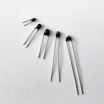
Choose an NTC thermistor when the span is narrow, resolution near ambient matters more than absolute range, and unit cost is under pressure. The selection detail for the thermistor side is in the NTC thermistor guide.
Every resistance figure here is calculated from the IEC 60751 coefficients printed above and can be recomputed independently.
The tolerance formulas are as defined in the standard, and the validity window attached to each class is stated in the standard rather than reproduced here, because those windows depend on element construction and on the edition in force.
The self-heating figures are worked from the excitation current and nominal resistance. The resulting temperature error depends on the dissipation constant of the specific probe in the specific medium, which is a per-part figure. Request it against a part code rather than assuming a category value.
No.1 XiSan Road, Electromechanical Industry Park , High&New Tech.Zone. Hefei,Anhui,China
Tel : +86-551-69109668
Whatsapp : +86-13339100504
Email : info@focusens.com
Skype : melodyliu520






 +86-551-69109668