HVAC Temperature Sensor Types: Which One Do I Need?
Apr 23, 2026A wrong sensor selection rarely announces itself immediately. It shows up three months later as a comfort complaint, an energy bill that runs 10% over design, or a control loop that hunts without explanation. In OEM and BMS projects, I have traced more system problems back to sensor type mismatch or poor mounting than to any equipment fault. This guide gives you the selection logic that prevents those problems before installation.
An HVAC temperature sensor provides real-time input that directly affects comfort, efficiency, and control accuracy. It tells the controller whether to open a valve, slow a fan, switch a compressor stage, or hold steady. Even a 1°C reading error can cause a chilled water system to miscalculate thermal load by 8–12%, running equipment longer than necessary and masking developing faults. Belimo's HVAC sensor guidance and ASHRAE's control requirements both treat temperature sensing as part of the control system architecture, not a peripheral measurement step.
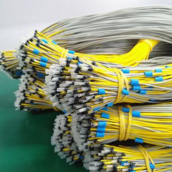
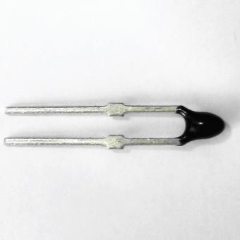
They convert temperature changes into electrical signals that controllers can read and act on. RTDs change resistance as temperature rises. Thermistors do the same but with a sharper, nonlinear curve over a narrower band. Thermocouples generate a small voltage at the junction of two dissimilar metals. The controller and signal interface matter as much as the sensing element itself — a high-accuracy RTD wired into the wrong input card delivers the same result as a cheap sensor installed correctly.
The three types covering nearly all HVAC design decisions are thermistors, RTDs, and thermocouples. Thermistors handle cost-sensitive control points inside normal operating ranges. RTDs provide accuracy and long-term stability for BMS and energy-critical loops. Thermocouples take over when the environment is too hot or too harsh for either alternative.
| Feature | Thermistor | RTD | Thermocouple |
|---|---|---|---|
| Accuracy | High within normal HVAC range | Very high | Medium |
| Temperature range | -40°C to +125°C typical | -200°C to +600°C | -200°C to +1,250°C |
| Response speed | Fast | Medium | Fast |
| Long-term stability | Good | Excellent | Good to fair |
| Relative cost | Low | Medium–High | Low–Medium |
| Typical HVAC use | Duct sensing, room control | BMS, energy metering, chilled water | Boiler stacks, exhaust, high-temp process |
The cost difference matters at scale: in a 200-point BMS installation, specifying RTD across every point instead of thermistors where thermistors are adequate can add significant hardware cost with no control benefit.
RTDs. Specifically Pt100 and Pt1000 types, which maintain a stable, repeatable resistance relationship that holds within tight tolerances over years of operation. For applications where drift compounds into energy miscalculation or control instability — chilled water ΔT monitoring, supply air reset strategies, energy sub-metering — RTDs are the engineering-sound choice. Thermistors are accurate within their operating range but more susceptible to drift under sustained humidity or thermal cycling.
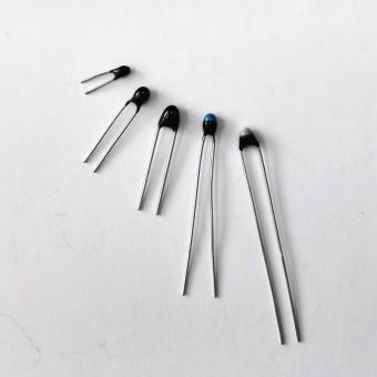
Use a thermistor when the measurement point is inside a normal HVAC operating band (roughly -10°C to +80°C), cost matters, and fast response is an advantage. Room sensing, duct sensing, return air monitoring, and freeze protection are all applications where thermistor performance is sufficient and the cost-to-accuracy trade is favorable. The majority of residential and light commercial HVAC systems are built on thermistor-type sensing — not as a budget compromise, but because the application does not require more.
Thermocouples are the correct choice when temperature range or environmental harshness rules out the alternatives. In standard HVAC work, that means boiler flue stacks, exhaust air discharge points, high-temperature process zones, or any location where sustained temperatures exceed what an RTD housing can tolerate. For chilled water, mixed air, or room sensing — environments where thermocouples are sometimes specified "because they're industrial" — they introduce signal noise and calibration overhead that thermistors and RTDs avoid entirely.
Work through this in order. Each factor narrows the field before you reach the catalog.
Control target — Room, duct, pipe, coil, outdoor air, or process water. This determines the probe format and IP rating before anything else.
Required accuracy — Comfort control tolerates ±0.5°C. Energy optimization and BMS control loops need ±0.1°C, which means RTD.
Temperature range — If the application stays within -40°C to +125°C, a thermistor is adequate. Beyond that, RTD. Beyond RTD's range, thermocouple.
Response speed — Fast correction loops (freeze protection, discharge air control) favor thermistors. Slower stabilization loops (room sensing, return air) are less sensitive to response time.
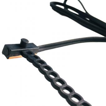
Mounting method — Immersion, clamp-on, duct probe, wall sensor, or outdoor housing. The installation format often eliminates options before sensor type is even discussed.
Controller input — Analog point, resistance input, or building automation interface. A Pt100 RTD wired to a controller expecting a 10kΩ thermistor input produces garbage data regardless of sensor quality.
Serviceability — Can the probe be tested, replaced, and calibrated without system shutdown?
Directly and measurably. If the controller reads a space as 0.8°C cooler than actual, it runs cooling longer than necessary — every cycle. Across a full operating season in a commercial building, that compounding error shows up in utility bills before it shows up in comfort complaints. ASHRAE's accuracy requirements reflect this: temperature sensing is part of the energy strategy, not a measurement formality. In one chilled water audit we supported, correcting two drifted RTDs reduced measured energy consumption by 7% without touching the mechanical plant.
Placement governs real-world accuracy more than sensor specification. A correctly specified sensor in the wrong location is operationally identical to a bad sensor.
Outdoor air: Away from direct sunlight, chimney exhaust, HVAC discharge, and any surface that absorbs or radiates heat. Radiation shields are not optional in exposed locations.
Room sensing: Mounted approximately 1.5m from floor, clear of exterior walls, direct sunlight, and local heat sources including occupant-level equipment.
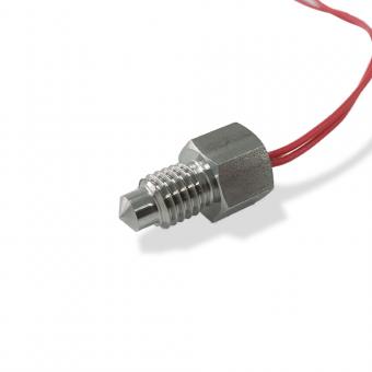
Immersion sensing (hydronic): Sensing element fully submerged in the medium. Insertion depth matters — a probe sitting in the boundary layer reads something between pipe temperature and ambient. For permanent chilled water or hot water monitoring, thermowell-mounted immersion probes eliminate the accuracy penalty of clamp-on alternatives. [Internal link: Focusens immersion probe series →]
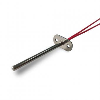
Duct sensing: Full probe length exposed to airflow. In ducts above 400mm or wherever mixing is incomplete after coils or dampers, a single-point probe can read several degrees away from the true average. [Internal link: HVAC duct averaging temperature probes →]
Mixed-water sensing: Maintain proper distance from the mixing point to allow complete mixing before measurement.
System accuracy is always worse than sensor accuracy, and the gap is larger than most specifications acknowledge. A sensor rated ±0.1°C installed in direct solar exposure, beside a hot surface, or with poor thermal contact will produce system errors of ±1°C or more. The complete measurement chain — sensor, mounting, wiring, controller input card, and scaling — each contributes error. Evaluating the sensor datasheet alone gives you the best-case number, not the operational number.
Most failures are installation or environment problems, not sensing element failures. In field diagnostics, checking the installation first resolves the majority of cases: loose clamp contact, condensation ingress through inadequate IP rating, vibration-loosened wiring, or a probe positioned where it measures local conditions rather than the medium of interest.
The failure patterns by sensor type:
A probe that passed factory QC and fails within 12 months almost always points to an IP rating mismatch with the actual environment, not a manufacturing defect.
Sensors feed controllers through analog inputs (resistance, voltage, or current) or digital building automation interfaces. The sensor output, scaling, and wiring must match what the controller expects — a Pt1000 RTD on a Pt100 input will read incorrectly but won't trigger a fault. Commissioning verification against a calibrated reference thermometer catches this before it runs undetected for a season.
There is no single best type — the application determines the answer.
| Application | Best Choice | Why |
|---|---|---|
| BMS energy metering, chilled water ΔT | RTD (Pt100/Pt1000) | Stable baseline, minimal drift over years |
| Room sensing, duct sensing, freeze protection | Thermistor (NTC) | Fast response, cost-effective in normal range |
| Boiler flue, exhaust stack, high-temp process | Thermocouple (Type K) | Only practical option above RTD range |
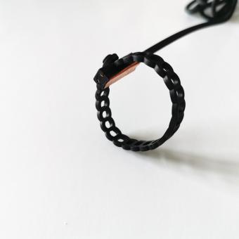
| Retrofit or diagnostic (no shutdown available) | Thermistor clamp-on | Fast deployment; accept accuracy trade-off |
| OEM integration, custom geometry required | Custom RTD or NTC | Housing, length, and connector matched to assembly |
Sensor selection is a control engineering decision made before the catalog is opened. The sensor type, mounting format, and placement are all determined by the application — the medium, the temperature range, the accuracy the control loop actually requires, and the installation constraints. RTD, thermistor, and thermocouple each solve a specific engineering problem; none is universally better than the others.
The highest-return action for most HVAC projects is not upgrading to a more accurate sensor — it is verifying that the current sensor type matches the application and that the installation puts it in genuine thermal contact with what it is supposed to measure.
For application-specific guidance on NTC, RTD, or custom probe selection, [contact the Focusens application engineering team →] or [browse our HVAC sensor catalog →].
No.1 XiSan Road, Electromechanical Industry Park , High&New Tech.Zone. Hefei,Anhui,China
Tel : +86-551-69109668
Whatsapp : +86-13339100504
Email : info@focusens.com
Skype : melodyliu520


freundliche Verbindungen :


 +86-551-69109668