How to Test a PTC Thermistor With a Multimeter
Oct 09, 2024
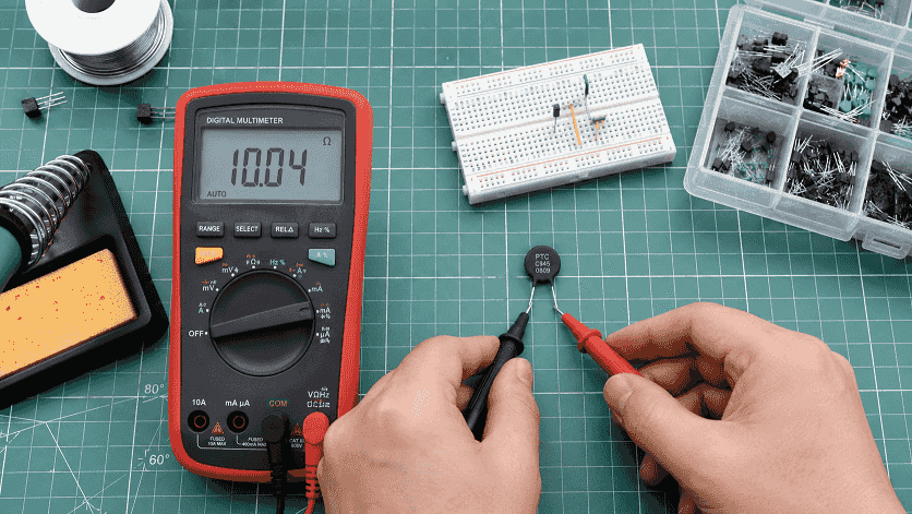
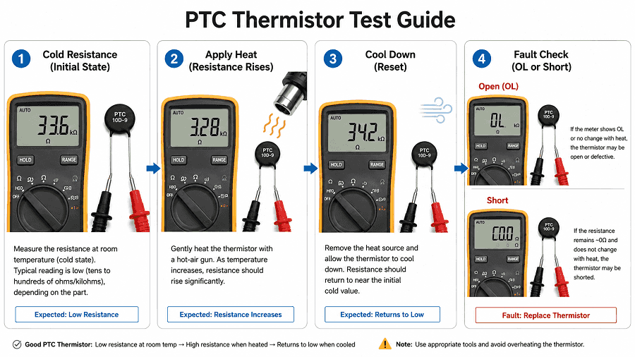
Direct answer: To test a PTC thermistor, power off the circuit, isolate at least one lead, set the multimeter to ohms, and measure the cold resistance near 20-25 C. Then apply gentle heat and watch the reading. A working PTC increases resistance as it warms and drops back after cooling. OL when cold usually means open; near-zero ohms usually means a short or wiring fault.
A multimeter test can tell you whether the PTC is open, shorted, responding to heat, resetting after cooling, or possibly not a PTC at all. It is useful for repair screening, incoming inspection and field diagnosis.
It cannot fully certify the rated switching temperature of a motor-protection PTC unless the test uses controlled temperature equipment and the correct datasheet limits. For safety-critical motor protection, use the multimeter test as a first check, then confirm the TK/TNAT and relay compatibility before replacement.
Power off and discharge the equipment before measuring. If the PTC is still connected to a board, relay input or motor circuit, disconnect one lead or unplug the sensor where practical. In-circuit testing can confirm a gross open or short, but it can also hide the real PTC value behind parallel components.
Do not use a flame. Do not overheat a small bead or motor winding sensor just to force an OL reading. The goal is to confirm a rising resistance trend and reset behavior, not to destroy the part.
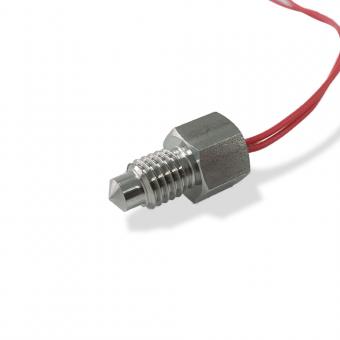
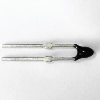
For a small ceramic switching PTC, the cold value may be low ohms to a few hundred ohms depending on the part. For silicon PTC/KTY-style sensors, the room-temperature value is often around 1 kOhm. Always use the datasheet as the pass/fail reference.
Key diagnostic rule: cold resistance alone is not enough. It proves continuity and rough value only. A real PTC diagnosis needs the direction of resistance change with heat and the cool-down reset check.
Motor-protection PTCs are not precision temperature sensors. They are limit sensors designed to stay low-resistance below the rated response temperature and rise steeply near TNAT/TK so a thermistor relay can trip.
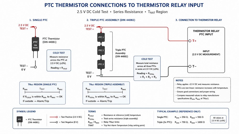
For DIN 44081 / DIN 44082 style motor-protection PTCs:
Example relay context: ABB CM-MSS thermistor motor-protection relays list overtemperature trip behavior around 2.83 kOhm total sensor-circuit resistance and reset after cooling around 1.1-1.2 kOhm, depending on model. Treat this as a relay-specific example, not a universal threshold. Always check the relay datasheet used in the equipment.
You can sometimes check a PTC in-circuit for obvious faults:
If the result affects a repair, replacement order or motor safety decision, isolate the PTC and compare with the datasheet before making the final call.
A PTC thermistor has a positive temperature coefficient: its resistance increases as temperature rises. An NTC thermistor does the opposite: resistance decreases as temperature rises.
If the unknown part drops in resistance when warmed, do not call it a failed PTC first. Treat it as an NTC candidate, check the part marking, and link the reader to the NTC vs PTC thermistor guide.
If the test shows an open, shorted or non-resetting PTC, collect the application data before quoting a replacement:
CTA: Need a replacement PTC thermistor or MZ6 motor-protection assembly? Send Focusens the cold resistance, TK/TNAT value, sensor count, cable length, insulation requirement and relay model. Link this CTA to the PTC thermistor range and MZ6 product pages.
What should a PTC thermistor read on a multimeter?
It should read its rated cold resistance at room temperature. Ceramic switching PTCs may read from low ohms to a few hundred ohms, while silicon PTC/KTY-style sensors are often around 1 kOhm. Use the datasheet value as the pass/fail reference.
How do I know if a PTC thermistor is bad?
OL when cold suggests an open sensor or broken lead. Near-zero ohms suggests a short. No resistance change with heat suggests the PTC effect is lost. Staying high after cooling suggests the part is damaged or still thermally tripped.
Can I test a PTC thermistor in-circuit?
Only for rough screening. In-circuit readings can be distorted by parallel resistors, relay inputs, controller circuits or cable faults. For a real pass/fail decision, isolate one lead or unplug the sensor and retest.
Does polarity matter when measuring a PTC with a multimeter?
For a two-lead ceramic PTC, polarity does not matter in resistance mode. For silicon PTC/KTY-style sensors, check the datasheet for operating polarity, but the basic resistance reading can still be used for identification.
Why does my meter show OL when I heat the PTC?
That can be normal for a switching PTC if it has reached the high-resistance region and the meter range is exceeded. It is a failure only if the part reads OL when cold or will not return after cooling.
Is cold resistance enough to verify a motor-protection PTC?
No. Cold resistance confirms continuity and approximate value. The protection function depends on the steep resistance rise near the rated response temperature TNAT/TK.
What is the DIN 44081 test voltage limit?
For room-temperature low-ohmic testing of DIN motor-protection PTCs, keep the test voltage at or below 2.5 V DC to avoid self-heating and misleading readings.
What if resistance falls when I apply heat?
That behavior points to an NTC thermistor, not a PTC thermistor. Re-check the part marking, application and datasheet before ordering a replacement.
No.1 XiSan Road, Electromechanical Industry Park , High&New Tech.Zone. Hefei,Anhui,China
Tel : +86-551-69109668
Whatsapp : +86-13339100504
Email : info@focusens.com
Skype : melodyliu520


freundliche Verbindungen :


 +86-551-69109668