How Pipe-Clamp Sensors Keep a 35°C Stadium Cool
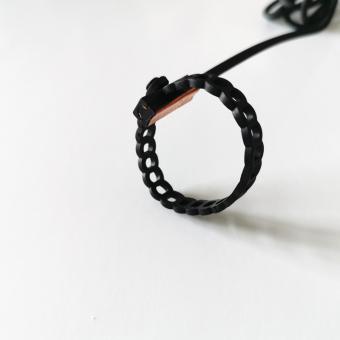
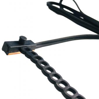
Jul 17, 2026Seventy thousand people in an enclosed bowl on a 35 °C afternoon is a cooling problem measured in megawatts. The equipment that solves it — chillers, pumps, air handlers, kilometres of insulated pipe — is photographed constantly and understood rarely. The component that decides whether any of it works is none of those things. It is a black plastic lozenge strapped to a pipe in a plant room, and it costs less than the bolts holding the chiller down.
Pull that sensor off its pipe and the chiller controlling the loop goes blind. A blind chiller is not a stopped chiller — that would at least be obvious. It is a chiller that keeps running against a number that is wrong, burning money quietly for the length of the tournament. This article walks the cooling chain from plant room to seat, and shows where clamp-on sensing decides the outcome.
Start with a figure most fans never hear. Chiller efficiency moves by roughly 2 percent for every 1 °F of change in chilled-water supply temperature. FacilitiesNet puts it at approximately 2 percent per degree of supply-temperature increase; Quest Design Group gives the same rule of thumb and notes paybacks under a year on larger plants. Georgia Power, quoted by BuildingIQ, is more conservative — about 1 percent per °F above 42 °F in centrifugal machines — with other sources landing between 1.5 and 2 percent. (FacilitiesNet; Quest Design Group; BuildingIQ citing Georgia Power.)
Call it 1–2 percent per degree and the conclusion holds either way.
This is not a rounding error dressed up as a story. It is the reason instrumentation appears in the standards at all. ASHRAE's Guideline 22, which defines how to instrument a central chilled-water plant, makes the same argument in standards language: the quality and installation of temperature instrumentation bounds how accurately plant efficiency can be known or controlled. (ASHRAE Guideline 22, Instrumentation for Monitoring Central Chilled-Water Plant Efficiency.) You cannot optimise what you cannot measure, and you cannot measure better than your sensor and its mounting allow.
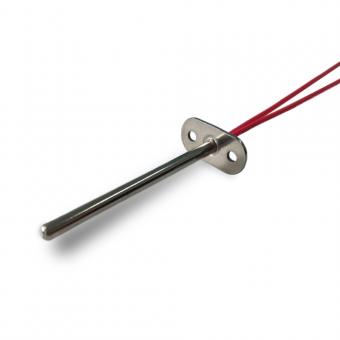
The chiller makes cold water, typically 6–7 °C (42–45 °F). It controls itself against two measurements above all others: water leaving, water returning. Those two normally use platinum RTDs — PT100 or PT1000 — because platinum drifts little and reads almost linearly against a defined curve. Focusensing's platinum elements follow DIN EN 60751: PT100 at R0 = 100 Ω and R100 = 138.5 Ω, PT1000 at R0 = 1000 Ω and R100 = 1385 Ω, in tolerance classes F0.15 (Class A) and F0.30 (Class B), TCR 3850 ppm/K. (Focusens quick-look catalogue.)
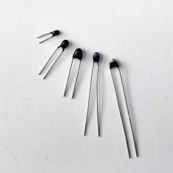
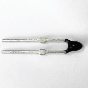
On the refrigerant side of the same machine the calculus flips. Suction and discharge points want speed and cost more than they want linearity, so NTC thermistors do that work. We break the plant-room split down in the chiller sensing article.
Chilled water leaves the plant and travels the building. Every branch, every riser, every header worth controlling gets a temperature. These are the points where cutting into the pipe is unattractive — the loop is full, it is insulated, and it is often already running. A clamp-on sensor goes on in minutes without breaking the wetted boundary, which is why distribution loops are where this format earns its place.
At the coil, chilled water meets air. The controller modulates a valve against coil-leaving temperature and against the water side. Get the water measurement wrong here and the valve hunts — the classic symptom of a sensor with more thermal lag than the control loop expects.
Everything above exists to put conditioned air at a body. The chain is only as good as its slowest, least accurate link, and in practice that link is almost never the chiller.
Here is the part product listings leave out. Two clamp-on sensors can carry the same NTC element, the same cable and the same strap — and read differently on the same pipe. The element is not what sets the reading. The thermal path between the pipe wall and the element is.
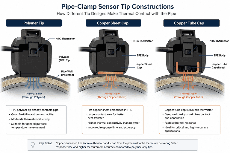
Heat has to cross from pipe surface into the thermistor through whatever sits in between. Three tip constructions are offered, and the choice sets response speed, steady-state error and ingress rating together — you cannot move one without moving the others.
| Tip construction | Thermal interface | Relative thermal lag* | Suited to |
|---|---|---|---|
| TPE overmould only | Polymer | Highest of the three | Slow points; slightly non-round surfaces |
| TPE + flat copper sheet cap | Copper, flat contact | Lower | General HVAC-R control |
| TPE + copper tube cap | Copper, deep coupling | Lowest of the three | Tight control loops, defrost termination |
* Relative ranking as given in the manufacturer's pipe-strap product documentation. It reflects the construction of the thermal path, not a measured time constant per variant — a per-tip response figure is not currently published. Where response time is a specification, request it in writing for the exact variant.
Why copper changes the answer: copper conducts heat at roughly 385 W/m·K, orders of magnitude better than the polymer around it. A bare polymer tip seals superbly and conducts poorly, so the sensor lags the pipe. A copper cap bridges that gap. A copper tube extends the bridge deeper toward the element. That is the whole trade — and it is a construction decision, not a grade decision. You cannot buy your way out of it with a tighter thermistor tolerance.
Which matters most on a stadium job? On a header you are trending, the polymer tip is fine. On a chilled-water loop the controller is actively modulating, the copper-sheet tip is the sensible default. On defrost termination, the copper tube — because there, lag is not an inconvenience, it is an iced coil.
| Parameter | Value | Source |
|---|---|---|
| Sensing element | NTC thermistor | Datasheet + catalogue |
| R25 | 10 kΩ ± 1 % | Datasheet + catalogue |
| B value | B25/85 = 3435 (3977 and others on request) | Datasheet + catalogue |
| Dielectric strength | AC 1500 V, 1 s, ≤ 1 mA | Datasheet + catalogue |
| Insulation resistance | ≥ 100 MΩ @ 500 V DC | Datasheet + catalogue |
| Cable | TPE jacket, 26 AWG | Datasheet + catalogue |
| Strap | 110 ± 10 mm × 7.0 ± 0.2 mm; locking holes 4.5 mm pitch | Pipe-strap documentation |
| Probe nose | 6.0 ± 0.5 mm | Pipe-strap documentation |
| Max pipe OD | ≈ 35 mm (extension strap available) | Pipe-strap documentation |
| Dissipation factor | 2.5 mW/°C | Catalogue |
| Long-term stability | drift 3 % after 1000 h at 80 °C / −30 °C | Catalogue |
| Response time | water (0.4 m/s), T0.63 = 30 s | Catalogue |
Read that last row carefully, because it is the row that gets misused. The response figure is measured in water. A still-air figure is a different measurement entirely. A sensor quoted at 30 s in water is not a 30-second sensor sitting on a dry pipe surface with a strap around it — and a stadium plant room is full of dry pipe surfaces.
Electrical parameters above appear consistently in the Focusensing pipe-strap product documentation and the Focusens product catalogue. Strap and probe dimensions are from the pipe-strap documentation. Dissipation factor, stability and response are from the catalogue. Variant part designations, operating temperature range and ingress ratings differ between current documents and are omitted here rather than guessed — request the current datasheet and specify against that.
Send these and a quotation with the matching build comes back: pipe OD and material · medium and its temperature range · control task (trend / modulate / defrost) · required response · ingress conditions · cable length and connector · the R25 and B curve your controller expects · certification required · annual quantity · target market.
Request the current datasheet → · Discuss your application →
No.1 XiSan Road, Electromechanical Industry Park , High&New Tech.Zone. Hefei,Anhui,China
Tel : +86-551-69109668
Whatsapp : +86-13339100504
Email : info@focusens.com
Skype : melodyliu520






 +86-551-69109668